%20(8)_edited.jpg)
%20(10).png)
Soft Foot
Soft foot occurs when there is inadequate surface contact between the underside of one of the equipment’s feet and the mounting surface of the equipment's baseplate. A simple way to think of soft foot is that it is similar to being seated on an unstable chair. The chair rocks because at least one leg does not come in perfect contact with the floor. For a chair, this is annoying but with industrial equipment, this condition will cause misalignment and will end with equipment damage such as cracked mounting feet. For successful and long-term equipment operation, soft foot must be eliminated before making any final alignment corrections.
Types of Soft Foot
Parallel Soft Foot – Parallel soft foot (Figure 1) is simply when one of the equipment's feet does not reach the base and a gap is created between the foot and base. The under side of the foot is parallel to the base plate. Tightening the hold-down bolt causes a distortion of the equipment’s frame as the soft foot is pulled into contact with the base. Parallel soft foot is easiest to detect using either a feeler gauge or dial indicator.

Figure 1 - Parallel Soft Foot
Angular Soft Foot – Angular soft foot (Figure 2) is when the equipment's foot is touching the base on either the outside or inside portion of the foot. The other portion of the foot, however, is machined (or bent) such that an angle between the base and the underside of the equipment foot occurs. Tightening the hold-down bolts will result in a distortion of the machine’s frame as the foot is drawn down to the base.

Figure 2 - Angular Soft Foot
Squishy Foot – Squishy foot (Figure 3), sometimes called spring foot, happens when shims are already installed between the equipment's foot and the surface that it is to be mounted on. The machine will appear to be fixed of soft foot problems until the hold-down bolts are tightened. Tightening the hold-down bolts can compress shims that are creased, bent, or otherwise damaged. This condition can distort the machine’s frame as the foot is drawn down to the base.
Squishy foot can also occur when an excessive amount of debris builds up under the machine foot or on top of the mounting surface. Debris build up can happen when loosening the bolts during an initial misalignment check as this process can release sediment and debris. Squishy foot from debris is a frequent problem for equipment that had been running for long periods of time in the field and is being restarted after a maintenance operation.

Figure 3- Squishy (Spring) Soft Foot
Stress-Induced Soft Foot – Not seen during fabrication and only experienced in the field, the most difficult soft foot condition to detect is caused by forces that are external to the equipment. Referred to as stress-induced soft foot (Figure 4), it can be the result of; pipe loads and moments; loads from large electrical connections on big motors; foundation design issues and other installation faults.

Figure 4 - Stress Induced Soft Foot
Effects of Soft Foot
Frame Distortion and Shaft Movement – The foremost concern of uncorrected soft foot is that after the machine is tightened down, the centerline of the shaft will be forced to shift due to the equipment frame becoming distorted. Frame distortion occurs when the soft foot is forced to mate with the mounting surface.
Any kind of shaft movement causes significant trouble when completing an alignment process and is a main cause of premature coupling, bearing, and mechanical seal failures.
Internal Misalignment – Internal components can be forced out of alignment due to frame distortions caused by an uncorrected soft foot.
Distorted Bearing Housing – Machine frame distortion can distort the bearing housing. This can result in excessive wear on the top and bottom of the outer race and lead to premature failure.
Fretting Corrosion – Persistent vibration can cause the bolts holding a motor to its foundation to become loose. A motor with a soft foot is more likely to cause fretting corrosion and repetitive impact damage to its foundation and bolts. Fatigue cracks in cast motor feet can also develop.
Detecting Soft Foot at the Mechanical Run Test
During the mechanical run test, soft foot will present with a dominant 1x RPM frequency reading in the vertical direction (Figure 5). Soft foot will be distinguishable from other typical 1x RPM dominant readings, such as rotor balance, by measuring the response on the top of the equipment foot and the top of the mounting surface. Phase response analysis will reveal that these two readings will be 180 degrees out of phase.
As well as phase vibration readings, soft foot can be confirmed by loosening bolts and measuring the resulting movement with a dial gauge. Equipment feet should be shimmed to obtain less than 0.002-in. (0.051-mm) movement.
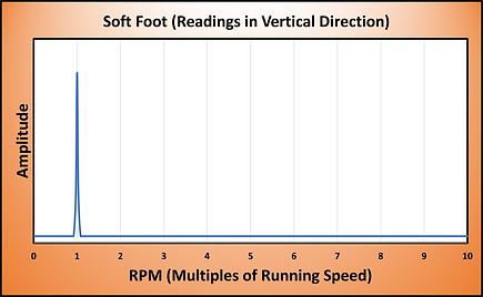
Figure 5 - Soft Foot Vibration Response