%20(8)_edited.jpg)
Impeller Balance Quality Assurance

WELDED BALANCE WEIGHTS
When welded, balance weights should be welded to the impeller using the same welding codes and standards that the rest of the impeller is fabricated to. If the welded balance weights are added by the balance machine operator, the welder qualifications of the operator should be reviewed during any witness balance operation by the inspector.
Unless stated otherwise by contract documents, balance weights should meet the following requirements:
-
The maximum thickness of the balance weight shall not exceed the lesser of either 1/4" (6mm) or the thickness of the impeller part the weight is welded to.
-
Balance weights shall be continuously welded.
-
Balance weight welds shall be subject to the same NDT requirements as the rest of the welded impeller assembly.
-
Balance weights shall be the same material as the welded impeller component to which they are welded.


BOLTED BALANCE WEIGHTS
For some impeller applications and when allowed by the purchaser, the balance of the impeller may need to be completed with the addition of balancing hardware (nuts, bolts and weights). The obvious risk to this method is that the hardware has the potential to come loose and detach during operation. Should balancing hardware be used, the inspector should be aware of the following items:
-
The material of the balancing hardware should be compatible with the impeller assembly so that galvanic corrosion between the hardware and the impeller is not promoted.
-
The tightening of the hardware must be completed with a calibrated torque wrench. The torque wrench calibration certificate should be reviewed during the balance inspection. The balance machine operator should demonstrate knowledge for the correct tightening torques.
-
Some equipment vendors may elect to use a thread locking compound to help keep the balancing hardware on the impeller. The locking compounds, however, do have maximum effective temperature. For equipment that will operate in elevated temperature applications, the suitability of the thread locking compound should be evaluated.


BALANCE BY MATERIAL REMOVAL
(GRINDING / DRILLING)
For applications where space inside the equipment casing is tight or when the impeller is cast, the balance of the impeller is often completed by removing material.
Each equipment vendor will have their own standards but when removing material from the impeller, the following should typically be observed by the inspector:
-
Grinded areas shall have a smooth transition to the not grinded areas and should be polished.
-
The balance operator should be aware of the minimum allowable thickness of the impeller shrouds/side plates after grinding.
-
Material removal should be away from the outer diameter and not go right up to the impeller's edge.
-
Material removal should be located in areas of the impeller where hydraulic and mechanical properties of the impeller are not affected. The grinded area should not be in the main fluid flow path.
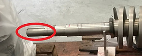
COMPLETE ROTOR BALANCE
For impellers that are balanced on a shaft as a complete rotor assembly, the inspector should check that the open keyways are filled with a crowned half key for the balancing operation. In addition, the mass and location of the half key should be recorded during any residual unbalance check